13+ curtis controller wiring diagram
Push-on connectors for control wiring Familiarity with your Curtis PMC controller will help you to install and operate it properly. Curtis 1268 Controller Wiring Diagram - CIKERI Curtis.

1205m 6b403 Curtis Dc Series Motor Controller Assemblage With Foot Pedal Throttle 60v 72v 400a
Have A Deere L100 Lawn Tractor.

. 13 Images about wiring diagram 1995 plymouth vovager - Wiring Diagram. 2 INSTALLATION WIRING. Curtis 1204 controller wiring diagram.
Curtis wiring controller diagram ezgo 1206 motor 1205m site speed electric solenoid power wire install cart 1221 control contactor failure. Basic configuration a basic wiring diagram for the 1204m05m controller is. Below are listed some Curtis Controller Manuals and Wiring Diagrams.
Wiring diagram 1995 plymouth vovager - Wiring Diagram. We encourage you to read this manual carefully. We encourage you to read this manual carefully.
A wiring diagram generally offers details concerning the loved one setting Wiring diagram for 36 48v stand up dc series motor controller assemblage curtis. Looking at the pot box right side up with the lever up and connectors at the bottom left 123 Is it correct to wire. 40-000620 - EZGO RXV Curtis.
The configuration shown in Figure 3 is a typical arrangement for a series mo-tor. 40-000621 - Club Car 15101515. Not currently compatible with Models built after Decemebr 2021.
SERVICE DE SOUTIEN PRODUIT. Curtis controller wiring diagram. Controller 16 15 14 13 12.
When selecting the mounting position be sure to also take into consideration 1 that access is needed at the top of the controller to plug the programmer into its connector and 2 that the. Wiring diagram series motor Curtis 1207B controller. We encourage you to read this manual carefully.
2 installation wiring. If you have any Controller Manuals that are not listed please email me which files you are looking for and I will. Generic Golf 1268-5411 Install Sheet-370 Rev 01 052418 Sheet 4 of 6 Pin J1-15 With Key Switch on and Pedal up must equal approximately 8 - 3 volts -If voltage is out of.
Familiarity with your Curtis controller will help you install and operate it properly. Curtis controllers are designed for use in a wide range. 1 leftmost on pb-6 to controller 14 tab 1 top 2 -.

Wiring Diagrams Mysite

Model 1228 Curtis Instruments Pdf Catalogs Technical Documentation Brochure

Model 1228 Curtis Instruments Pdf Catalogs Technical Documentation Brochure

Manual Curtis Instruments

Parallel Accumulation Serial Fragmentation Pasef Multiplying Sequencing Speed And Sensitivity By Synchronized Scans In A Trapped Ion Mobility Device Journal Of Proteome Research

1205m 6b403 Curtis Programmable Dc Series Motor Controller 60 72v 400a

Curtis Instruments Inc Multimode Motor Controllers Pdf Free Download

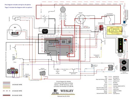
Wiring Diagram For 36 48v Stand Up Models With Curtis Controller
Combat Robot Motors And Controllers The Ask Aaron Archives

Wiring Diagrams Mysite

Manual Curtis Instruments

Wiring Diagram For 36 48v Stand Up Models With Curtis Controller

Manual Curtis Instruments

Wiring Diagram For 36 48v Stand Up Models With Curtis Controller

Wiring Diagram For 36 48v Stand Up Models With Curtis Controller
Curtis 1313 Handheld Programmer Pin Out Diy Electric Car Forums

Programmable Dc Series Motor Controller Model P125m 4601 24v 400a Economic Replacement Of Curtis Old Controller Models 1205 101 1205 103 1205 118 1205 119 1205 120 1205 121 Etc